
2.0 Introduction
In this lab we will take our base environment and then start to configure the systems to control the data flow.
2.1: Configure VNet to Vnet Connection
In our VDC environment, we have a hub virtual network (used as a central point for control and inspection of ingress / egress traffic between different zones) and a virtual network used to simulate an on-premises environment. In order to provide connectivity between the hub and on-premises, we will configure a site-to-site VPN. The VPN gateways required to achieve this have already been deployed, however they must be configured before traffic will flow. Follow the steps below to configure the site-to-site VPN connection.
1) Using the Azure portal, click on ‘All Services’ at the top left of the screen and then search for and select ‘Virtual Network Gateways’. Click on the virtual network gateway named ‘Hub-vpn-gw’. Select ‘Connections’.
2) Add a connection and name it ‘Hub2OnPrem’. Ensure the connection type is ‘VNet-to-VNet’.
3) Choose ‘OnPrem-vpn-gw’ as the second gateway.
4) Use ‘M1crosoft123’ as the shared key. Select ‘OK’ to complete the connection.
5) Repeat the process for the other VPN gateway (OnPrem-vpn-gw), but reverse the first and second gateways when creating the connection (name the connection ‘OnPrem2Hub’).
6) Under the resource group VDC-OnPrem navigate back to the OnPrem-vpn-gw virtual network gateway resource and then click ‘Connections’. You should see a successful VPN connection between the OnPrem and Hub VPN gateways.
Note: It may take a few minutes before a successful connection is shown between the gateways.
At this point, we can start to verify the connectivity we have set up. One of the ways we can do this is by inspecting the effective routes associated with a virtual machine. Let’s take a look at the effective routes associated with the OnPrem-vm virtual machine that resides in the OnPrem VNet.
6) Using the Azure portal, navigate to the OnPrem-vm-nic object under the VDC-OnPrem resource group. This object is the network interface associated with the OnPrem-vm virtual machine.
7) Under ‘Support + Troubleshooting’, select ‘Effective Routes’. You should see an entry for ‘virtual network gateway’, specifying an address range of 10.101.0.0/16, as shown in figure 4.
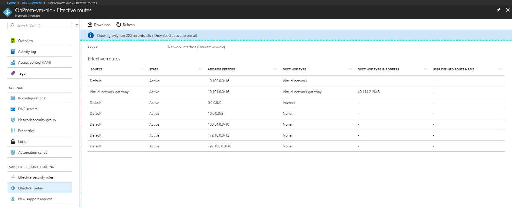
Figure 4: OnPrem-vm Effective Routes
Figure 5 shows a diagram explaining what we see when we view the effective routes of OnPrem_VM.
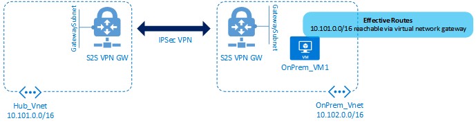
Figure 5: Routing from OnPrem-vm
Next, let’s move on to configuring our Cisco Network Virtual Appliances.
2.2: Configure the Cisco CSR 1000v
One of the requirements of many enterprise organisations is to provide a secure perimeter or DMZ environment using third party routers or firewall devices. Azure allows for this requirement to be met through the use of third party Network Virtual Appliances (NVAs). An NVA is essentially a virtual machine that runs specialised software, typically from a network equipment manufacturer, and that provides routing or firewall functionality within the Azure environment.
In our VDC environment, we are using Cisco CSR 1000v routers in the Hub virtual network - CSR stands for Cloud Services Router and is a virtualised Cisco router running IOS-XE software. The CSR 1000v is a fully featured Cisco router that supports most routing functionality, such as OSPF and BGP routing, IPSec VPNs and Zone Based Firewalls.
In the initial lab setup, you provisioned the CSR 1000v router in the Hub virtual network, however it must now be configured in order to route traffic. Follow the steps in this section to configure the CSR 1000v.
1) To log on to the CSR 1000v, you’ll need to obtain the public IP address assigned to it. You can obtain this using the Azure portal (navigate to the VDC-NVA resource group and inspect the object named ‘csr-pip’). Alternatively, you can use the Azure CLI to obtain the IP addresses for the virtual machine, as follows:
az vm list-ip-addresses --resource-group VDC-NVA --output table
VirtualMachine    PublicIPAddresses    PrivateIPAddresses
----------------  -------------------  --------------------
csr               51.144.132.127       10.101.1.4
csr                                    10.101.2.4
2) Now that you have the public IP address, SSH to the CSR 1000v VM from within the Cloud Shell using ‘ssh labuser@public-ip’. The username and password for the CSR are labuser / M1crosoft123.
3) Enter configuration mode on the CSR:
conf t
4) The CSR 1000v has two interfaces - one connected to Hub-vnet-subnet1 and the other connected to Hub-vnet-subnet2. We want to ensure that these interfaces are configured using DHCP, so use the following CLI config to ensure that this is the case and that the interfaces are both in the ‘up’ state:
csr(config)# interface gig1
csr(config-if)# ip address dhcp
csr(config-if)# no shutdown
csr(config)# interface gig2
csr(config-if)# ip address dhcp
csr(config-if)# no shutdown
csr(config-if)# exit
csr(config)# exit
csr# copy running-config startup-config
Destination filename [startup-config]?
Building configuration...
[OK]
5) Verify that the interfaces are up and configured with an IP address as follows:
csr# show ip interface brief
Interface              IP-Address      OK? Method Status                Protocol
GigabitEthernet1       10.101.1.4      YES DHCP   up                    up
GigabitEthernet2       10.101.2.4      YES DHCP   up                    up
6) Exit the SSH session to the Cisco CSR and then find the public IP address of the virtual machine named OnPrem-vm using the following command:
az vm list-ip-addresses --name OnPrem-vm --resource-group VDC-OnPrem --output table
7) SSH to the public IP of OnPrem-vm. From within the VM, attempt to connect to the private IP address of one of the CSR 1000v interfaces (10.101.1.4):
ssh labuser@10.101.1.4
This step should succeed, which proves connectivity between the On Premises and Hub VNets using the VPN connection. Figure 6 shows the connection we have just made.
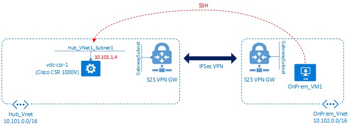
Figure 6: SSH from OnPrem-vm to csr
8) Exit the SSH session to the CSR 1000v and then exit the SSH session to the OnPrem virtual machine. You should now be back in the Cloud Shell session. Find the internal IP address of a virtual machine’s NIC in VDC-Spoke1, either by using the portal or any of the following CLI 2.0 commands:
az network nic ip-config list --resource-group VDC-Spoke1 --nic-name Spoke1-vm1-nic -o table
az network nic list --query "[].{group:resourceGroup, NIC:name, IPaddress:ipConfigurations[0].privateIpAddress}" -o table
The second command is more complicated, using a JMESPATH query to customise the output, but it does demonstrate the power that those commands can provide. If you wasnt to know more then look at the CLI 2.0, Bash and JMESPATH Tech Primer.
The VM’s IP address is expected to be 10.1.1.5 or 10.1.1.6 depending on the order in which the VM builds completed.
9) Log back in to OnPrem-vm, and then attempt to connect to the private IP address of the virtual machine within the Spoke 1 vNet.
(Note that the command below should fail and simply hang - use CTRL+C to cancel.)
ssh labuser@10.1.1.5
The reason for the failure is that we do not yet have the correct routing in place to allow connectivity between the OnPrem vNet and the Spoke vNets via the hub and the NVA. In the next section, we will configure the routing required to achieve this.
2.3: Configure User Defined Routes
In this section, we will configure a number of User Defined Routes. A UDR in Azure is a routing table that you as the user define, potentially overriding the default routing that Azure sets up for you. UDRs are generally required any time a Network Virtual Appliance (NVA) is deployed, such as the Cisco CSR router we are using in our lab. The goal of this exercise is to allow traffic to flow from VMs residing in the Spoke VNets, to the VM in the On Premises VNet. This traffic will flow through the Cisco CSR router in the Hub VNet. The diagram in figure 7 shows what we are trying to achieve in this section.
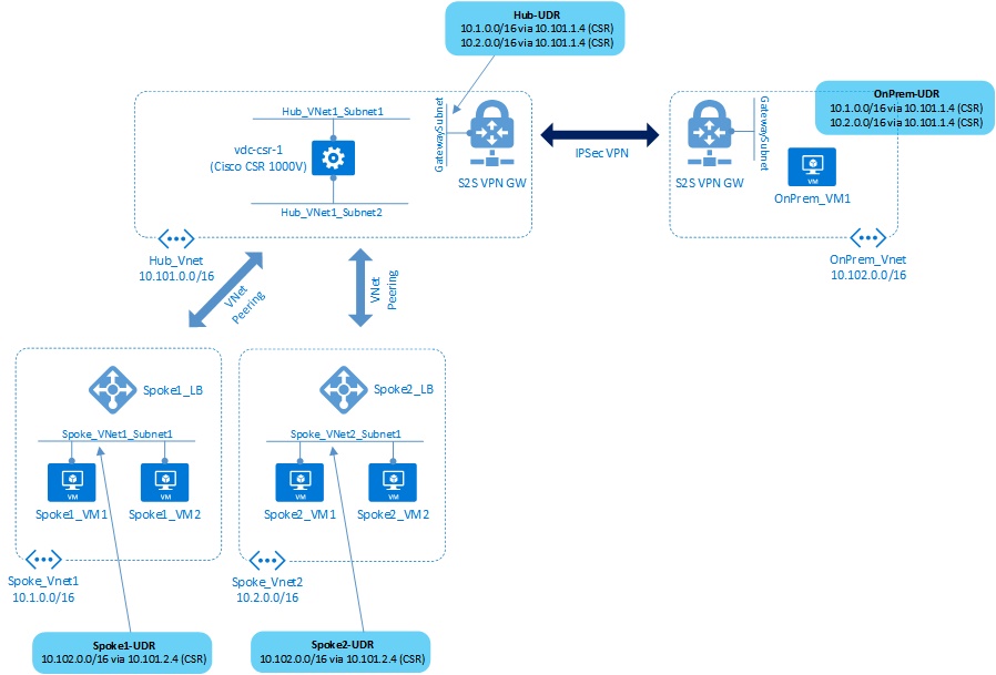
Figure 7: User Defined Routes
We’ll create our first User Defined Route using the Azure portal, with subsequent UDRs configured using the Azure CLI.
1) In the Azure portal, click ‘+ Create a resource’ and then search for ‘Route Table’. Select this and then create a new route table named OnPrem-UDR, making sure that a) you have selected the existing VDC-OnPrem resource group and b) it is in the ‘West Europe’ region. Once complete, navigate to the newly created UDR and select it.
2) Click on ‘Routes’ and then ‘Add’. Create a new route with the following parameters:
- Route Name: Spoke1-Route
- Address Prefix: 10.1.0.0/16
- Next Hop Type: Virtual Network Gateway
Click ‘OK’ to create the route. Repeat the process for Spoke 2 as follows:
- Route Name: Spoke2-Route
- Address Prefix: 10.2.0.0/16
- Next Hop Type: Virtual Network Gateway
Figure 8 shows the route creation screen.
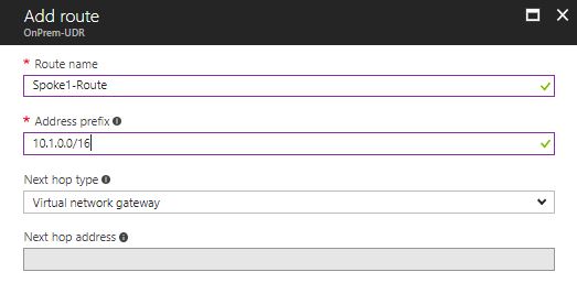
Figure 8: Defining UDRs
3) We now need to associate the UDR with a specific subnet. Click on ‘Subnets’ and then ‘Associate’. Select the VNet ‘OnPrem-vnet’ and then the subnet ‘OnPrem-vnet-subnet1’. Click OK to associate the UDR to the subnet.
We’ll now switch to the Azure CLI to define the rest of the UDRs that we need.
4) Create the UDR for the Hub Vnet (GatewaySubnet):
az network route-table create --name Hub-UDR -g VDC-Hub
5) Create the routes to point to Spoke1 and Spoke2, via the Cisco CSR router:
az network route-table route create --name Spoke1-Route --address-prefix 10.1.0.0/16 --next-hop-type VirtualAppliance --next-hop-ip-address 10.101.1.4 --route-table-name Hub-UDR -g VDC-Hub
az network route-table route create --name Spoke2-Route --address-prefix 10.2.0.0/16 --next-hop-type VirtualAppliance --next-hop-ip-address 10.101.1.4 --route-table-name Hub-UDR -g VDC-Hub
6) Associate the UDR with the GatewaySubnet inside the Hub Vnet:
az network vnet subnet update --name GatewaySubnet --vnet-name Hub-vnet --route-table Hub-UDR -g VDC-Hub
7) Configure the UDRs for the Spoke VNets, with relevant routes and associate to the subnets:
az network route-table create --name Spoke1-UDR -g VDC-Spoke1
az network route-table create --name Spoke2-UDR -g VDC-Spoke2

az network route-table route create --name OnPrem-Route --address-prefix 10.102.0.0/16 --next-hop-type VirtualAppliance --next-hop-ip-address 10.101.2.4 --route-table-name Spoke1-UDR -g VDC-Spoke1
az network route-table route create --name OnPrem-Route --address-prefix 10.102.0.0/16 --next-hop-type VirtualAppliance --next-hop-ip-address 10.101.2.4 --route-table-name Spoke2-UDR -g VDC-Spoke2

az network vnet subnet update --name Spoke1-vnet-subnet1 --vnet-name Spoke1-vnet --route-table Spoke1-UDR -g VDC-Spoke1
az network vnet subnet update --name Spoke2-vnet-subnet1 --vnet-name Spoke2-vnet --route-table Spoke2-UDR -g VDC-Spoke2
Great, everything is in place - we are now ready to test connectivity between our on-premises environment and the Spoke VNets.
2.4: Test Connectivity Between On-Premises and Spoke VNets
In this section, we’ll perform some simple tests to validate connectivity between our “on-premises” environment and the Spoke VNets - this communication should occur through the Cisco CSR router that resides in the Hub VNet.
1) SSH into the virtual machine named OnPrem-VM1 as you did earlier.
2) From within this VM, attempt to SSH to the first virtual machine inside the Spoke 1 virtual network (e.g. with an IP address of 10.1.1.5) - this will fail:
ssh labuser@10.1.1.5
Although we have all the routing we need configured, this connectivity is still failing. Why?
It turns out that there is an additional setting we must configure on the VNet peerings to allow this type of hub and spoke connectivity to happen. Follow these steps to make the required changes:
3) In the Azure portal, navigate to Spoke1-vnet in the ‘VDC-Spoke1’ resource group. Select ‘peerings’ and then select the ‘to-Hub-vnet’ peering. You’ll see that the option entitled Use Remote Gateways is unchecked. Checking this option allows the VNet to use a gateway in a remote virtual network - as we need our Spoke VNets to use a gateway residing in the Hub VNet, this is exactly what we need, so check the box as shown in figure 9.
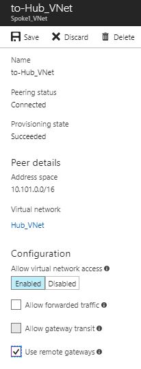
Figure 9: Use the Remote Gateway Option
4) From within the OnPrem-vm virtual machine, try to SSH to the Spoke VM once more. The connection attempt should now succeed.
5) Configure the Spoke 2 VNet peering with ‘Use Remote Network Gateway’ and then attempt to connect to one of the virtual machines in Spoke 2 (e.g. 10.2.1.5). This connection should also now succeed.
6) Still from the OnPrem-vm machine, use either the curl or lynx commands to make an HTTP request to the load balancer private IP address in Spoke1. (The curl command will return the raw HTML, whilst lynx has been installed so that you can view the page in a basic ASCII browser.)
Note that the IP address should be 10.1.1.4, however you may need to verify this in the portal or CLI:
curl http://10.1.1.4
lynx http://10.1.1.4
This command should return an HTML page showing some information, such as the page title, the hostname, system info and whether the application is running inside a container or not. (The curl command will return the raw HTML, whilst the lynx command should bring up a simple ASCII based browser.)
If you try the same request a number of times, you may notice that the response contains either Spoke1-VM1 or Spoke1-VM2 as the hostname, as the load balancer has both of these machines in the backend pool.
In the next section, we will lock down the environment to ensure that our On Premises user can only reach the required services.
Leave a comment